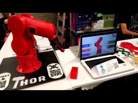
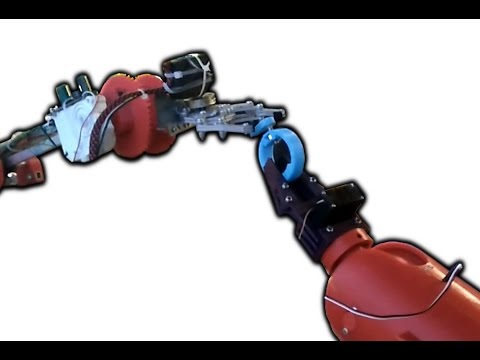
Thor is an open source, 3D printed, 6 degrees of freedom robotic arm. Designed to be affordable and accessible, Thor is ideal for educational settings, makers, and robotics enthusiasts. With a height of 625mm it has the capacity to lift up to 750g. Its yaw-roll-roll-yaw-roll-yaw configuration is common in industrial manipulators.

- 🧩 Born Open Source: Designed using open source software such as FreeCAD, KiCAD, GRBL, RRF and ROS.
- 🕊️ Released Open Source: All source files published under CC-BY-SA-4.0 license.
- 💰 Low Cost: Hardware cost below 350€.
- 📚 Suitable for education: Perfect for robotics courses in schools and universities, there are already success cases!
- 🧰 G-code Controlled: Uses the same language as 3d printers and CNCs to move.
- 🐳 ROS2 Integration: Available implementation using Docker for flexibility.
freecad-src– Source files of 3D models created with FreeCADmods– Modified models and improvements to standard modelsstl– Printable STL filesstep– STEP files
- Thor-ROS: ROS2 & Moveit2 configuration files and packages to work with Thor.
- ThorControlPCB: Source & manufacture files of Arduino Mega shield designed to control Thor.
- Asgard: Control software for thor motors with a simple interface.
- Read the Documentation: Comprehensive guides on printing, assembly, electronics, and firmware are available at thor.angel-lm.com/documentation.
- Print the Parts: Use the STL files in this repository.
- Get the Hardware: Take a look to the Bill of Materials.
- Assemble the Robot: See here for assembly videos and interactive instructions.
- Assemble & Setup the Electronics: The Wiring & Setup guide will help you prepare your electronic board and make the hardware connections.
- Install the Firmware: Depending on which electronics you have chosen, you will have to perform a different firmware configuration. This page explains the steps to follow.
- Control the Robot: Use Asgard to move the robot. Here is how to do it.
- Degrees of Freedom: 6 (yaw-roll-roll-yaw-roll-yaw).
- Height Stretched: 625mm (without end effector).
- Payload Capacity: 750g max (including end effector weight).
- Motors: Stepper motors.
- Electronics: DIY PCB or commercial boards.
- Transmission: 3D printed gears, GT2 pulleys and belts.
- Software: FreeCAD, KiCAD, GRBL, RRF, ROS2.
- 🌐 Official Website: thor.angel-lm.com
- ❓ Frequently Asked Questions: FAQ
- 💬 Thor Community Forums: Thor Forums
- 💬 Thor Discord Server: Thor Robot Community
Contributions are welcome! If you'd like to improve Thor — whether it's design, documentation, or code — feel free to open an Issue or submit a Pull Request.
This repository also carries a solid-node simulation layer under
simulation/: the whole machine assembled from its own published parts, six
joints and a gripper a maker can drive in a browser, and contracts that fail
when an interface stops holding. Nothing under stl/, step/,
freecad-src/, mods/ or doc/ is edited by it — the printed parts are
read from step/*.step as they are, and every placement comes from the
FreeCAD Assembly4 documents' own solved values.
With solid-node installed:
solid build                       # build once and publish the model
solid develop                     # a live viewer that rebuilds on save
solid test --exact simulation/thor.py     # the contracts
solid snapshot -o thor.png --autocenter --viewall
The contracts run on the exact kernel and only on it. Seven of Thor's
printed parts tessellate to a mesh that is not closed at the default
deflection — their solids are sound — and the faceted kernel refuses those
meshes rather than answering, so --faceted cannot run this machine.
| driver | what it measures | range |
|---|---|---|
art1 |
the base's yaw about Z | ±180° |
art2 |
the shoulder's roll about Y, 202.0 mm up | ±90° |
art3 |
the forearm's roll in the machine frame | ±135° |
art4 |
the forearm's yaw about its own axis | ±180° |
art5 |
the wrist's roll about Y, 556.0 mm up | ±105° |
art6 |
the tool's roll about the wrist output axis | ±180° |
grip |
the clear opening between the two jaws | 0–69.94 mm |
art3 is absolute, not relative to the upper arm, because the machine is:
the belt that sets the elbow runs from a pulley carried by the shoulder
housing rather than by the arm. Swing art2 alone and the forearm keeps
pointing the same way while no elbow motor turns. The published joint
limits are not in this repository, so the ranges above are the mechanism's
own travel where the geometry bounds it and the full circle otherwise;
they are presentation only and clamp nothing.
The instructions are Home, Ready, Reach, Pick, Place and Park.
A scenario contract triggers all six in order, at the rate each joint's own
mechanism allows, and asks the machine on the way whether it has driven any
part through another.
Each sub-assembly builds on its own, in the order the robot stands up:
solid build simulation/base.py:Base       # the plinth and the electronics box
solid build simulation/art1.py:Art1       # the shoulder housing and up
solid build simulation/art2.py:Art2       # the upper arm and up
solid build simulation/art3.py:Art3       # the elbow's output link and up
solid build simulation/art4.py:Art4       # the forearm and the wrist
solid build simulation/art56.py:Art56     # the wrist differential and gripper
solid build simulation/gripper.py:Gripper # the end effector aloneAssembling Thor in software is the first time anything has asked its files
every question at once, and some of the answers are worth having. All of
these are measured; docs/measurements.md carries the numbers and how they
were read, and none of them is fixed upstream.
- The elbow-to-wrist span is 194.0 mm, not the 195.00 the axis drawing states. The drawing's other two spans, 202.00 and 160.00, match the assembly exactly.
- No gear pair in the assembly is phased to mesh. All five printed pairs interpenetrate at the pose the assembly records, by 0.2 to 46.2 mm³. A builder puts a pinion on at an angle that drops into mesh; the model measures that angle for each pair.
- The two shoulder pinions need different angles — 31.5° and 19.5° — although the design places them symmetrically. They are mirrored instances of one part.
- The base pinion has no interference-free angle at all. It stands 2 mm taller than the ring gear it drives, and its top rim cuts the rim above the teeth by 0.20 mm³ whatever angle it is put on.
- The forearm pinion's lower flange fouls the column's gear by 24.30 mm³ at every angle: the flange is 1.2 mm larger in radius than the teeth, and the ring at the foot of the column's gear is not relieved for it.
- The arm's two sprung tensioners do not reach its belt. The taut run between the shoulder and elbow pulleys passes 5.41 mm clear of their rims, so they are drawn retracted and the belt is a plain two-pulley loop of 462.98 mm — 231.5 teeth, which is what the tensioners are there to take up.
- The arm's two belt pulleys share only 3.65 mm of land for a 6 mm belt. Their running surfaces overlap between 18.000 and 21.651 along the shoulder axis and nowhere else. The forearm's pulleys share their whole 7.5 mm land, which is how you know this one is the arm's.
- The forearm belts are named for 208 mm and their pulleys need 223.5 mm. The design's own belt solid measures about 220, so it is the name that is wrong — but a builder buying by the name gets a belt that will not close.
- All three belt solids are placed where their pulleys are not. Both forearm belts lie flat in a plane perpendicular to their pulleys' axes, and the arm's belt clears both of its own pulleys.
Art1Topis one solid that tessellates into five bodies — the part, three zero-volume patches and a detached lug — which is why every question here is asked of the solids.- The wrist's belt pulleys are 4 mm-bore pulleys on a 5 mm shaft. The
design's own
GT2x40PulleyM4is bored 2.000 in radius and its ownShaft_5x102mmis 2.500, so half a millimetre of bore wall is solid shaft over the pulley's whole 17 mm.
The interference contract that finds these is red on purpose: 272
pairs of solids share space at the home pose and thirteen are recorded, so
the model is still telling the truth about how much it has explained.
docs/measurements.md breaks the rest down.
GripperBotis sunk 3248.9 mm³ intoArt56GearPlate. The gripper base's mounting boss occupies the same space as the plate it bolts to; neither part rebates for the other.Art4Optodiskpasses 24.1 mm³ throughArt3Body's wall rather than running in a slot cut for it.Art2MotorGearandArt4BodyBotare exported inside out, measuring −8435.0 and −113674.9 mm³.GripperActiveArmandGripperPassiveArmeach hold two solids: the arm, and a loose Ø3.4 × 5.0 pin standing in its outer pivot hole. A builder slicing those files gets a plug printed inside the hole.GripperFingeris used mirrored but published only one way, so a builder printing fromstep/orstl/gets two identical jaws rather than the handed pair the assembly uses.Art1OptoFix,Art4BearingPlugandArt56Interfaceare drawn and exported but placed in no assembly.- The design models no fastener. Every screw and nut in the model is derived from the parts' own Ø3.4 holes, Ø5.9 counterbores and 5.80 across-flats pockets: 181 fasteners, 77 of them with nuts, and 85 further hole stacks the geometry cannot classify.
Thor is licensed under the Creative Commons Attribution-ShareAlike 4.0 International License. You’re free to use, modify, and distribute this project under its terms.